Part II. After disassembly, restoring and reassembling the hull and suspension was the next step.
Tiger 131 was captured in April 1943. In September 1951 it was passed to the Tank Museum where it soon became one of the most famous vehicles in the collection. In 1990 it was decided to restore the tank to running order. Battle damage would not be repaired.
In November 1999 the Tank Museum created a website to track the restoration project. This site featured monthly updates for 4 years. This series of posts will republish some of the photographs and details featured on that site, and then bring the story of Tiger 131’s restoration up to date.
Reassembly of the suspension, tracks and wheels
Reconstructing the hull began in early 1992. The first job was to paint it with a coat of rust-proof grey paint followed by red-oxide primer. The interior was also repainted.
After this, work began on reassembling the suspension system.
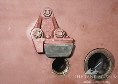
In this view we are looking at one of the brackets, mounted on the hull side above the extreme front and rear axle arms, which holds a rubber block to act as a bump stop. Notice how, as with most German tank components, part numbers are actually cast into the item.
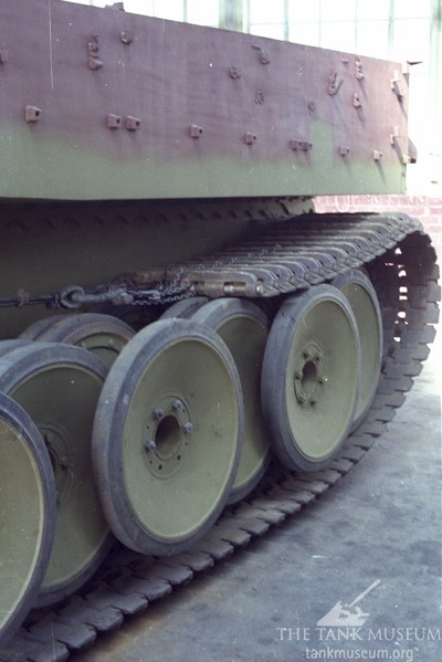
By the summer of 1993 a start had been made on re-assembling the suspension. Here tyres are fitted back onto the road wheels, having been removed so that rust could be cleaned out of the rim.

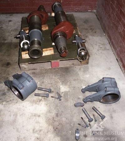
The next stage was to insert the road wheel arms, which would then be linked up to the torsion bars. This was painstaking work, the items were heavy but they had to be fitted with the greatest care to avoid the risk of damage.
The next stage was to insert the torsion bars themselves and it is interesting to note that they are not as heavy as one might expect. This particular bar links with a road wheel station on the opposite side of the tank.
Here we see the torsion bars all in place. Notice how they alternate left and right, and the way they are anchored in a splined sleeve to hold them as they twist.

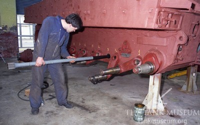
After refitting the road wheels to their arms it was time to replace the tracks, and this was no easy job. The hull was rolled onto the tracks and then they were carefully drawn around the rear idler and along the top as this view shows.
The next stage was to connect the tracks and above we can see ‘Chatty’ Taylor preparing to insert the final pin. Once this is in place and secured the tracks will be adjusted for tension by moving the idlers and the hull will be ready to roll.
Putting the hull together
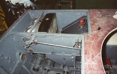
Meanwhile progress was being made inside the hull.
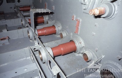
The shaft above and to the right is the mounting for a shock absorber which also connects with the link arm on the leading torsion bar below.
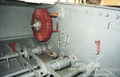
The next stage was to install the radiators and cooling fans. Notice how these were located in separate compartments either side of the engine bay. The fuel tanks were installed at the same time. This view also shows the drive system that connected the original HL210 engine to the cooling fans.
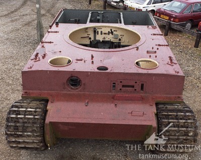
With the tracks fitted it was now possible to move the hull and in March 1994 it was hauled out onto the Museum car park for a TV promotion. Here we have an overhead view from the front which shows that there was still a lot of work to be done.
See Part I: Disassembly and Part III: Restoring the Turret.